
Amongst full scale helicopter pilots, the Hughes 500-series is known for it's good handling and powerful performance because it's an airborne hot rod so powerful they kept adding blades until they could fully harness the engine! Anyway, if you admire this fabulous flying Ferrari,then you're in the right place because we're going to show you how to roll your own by installing a set of our reliable Pantera P6 mechanics into a Funkey-brand 600-class Hughes 500D fuselage. And there's a ink to a Hugh 500 history and background article to get you started on paint schemes!
All hat said, it's important to recognize is what follows; these are useful tips for slipping any brand of mechanics into any fiberglass fuselage! The steps are pretty much always the same, check vertical fit and center main shaft in the opening, square the tail boom with the fuselage tail boom, either block the frame higher, and chop it down to fit as as needed, and go for it.
Once the mechanics are installed, then remove them and begin detailing with paint, decals, and what not to your heart's content. When is it finished? When you stop working!


History & Background
Note; if background info bores you to tears, then skip this accordion because it won't impede installation (or hurt my feelings). It's only for helping understand why the Hughes airframe is so tiny compared to a competing Jet Ranger, why it has more than 2-blades, and principally serves as an overview of the mark. So while useful when deciding if you want to build a civilian or military scheme, and in distinguishing between the various versions, it's not critical as regards installing a set of mechanics into a fiberglass fuselage.
https://www.audacitymodels.com/articles/airframe/hughes-500-history-and-background
Installation – pictorial guide
We're going to specifically focus on Shayne Hoerchel's photos showing how he slips a set of mechanics into a Funkey-brand 600-class Huges 500D. It's fun and easy and the results are fantastic . . . a bespoke scale model!
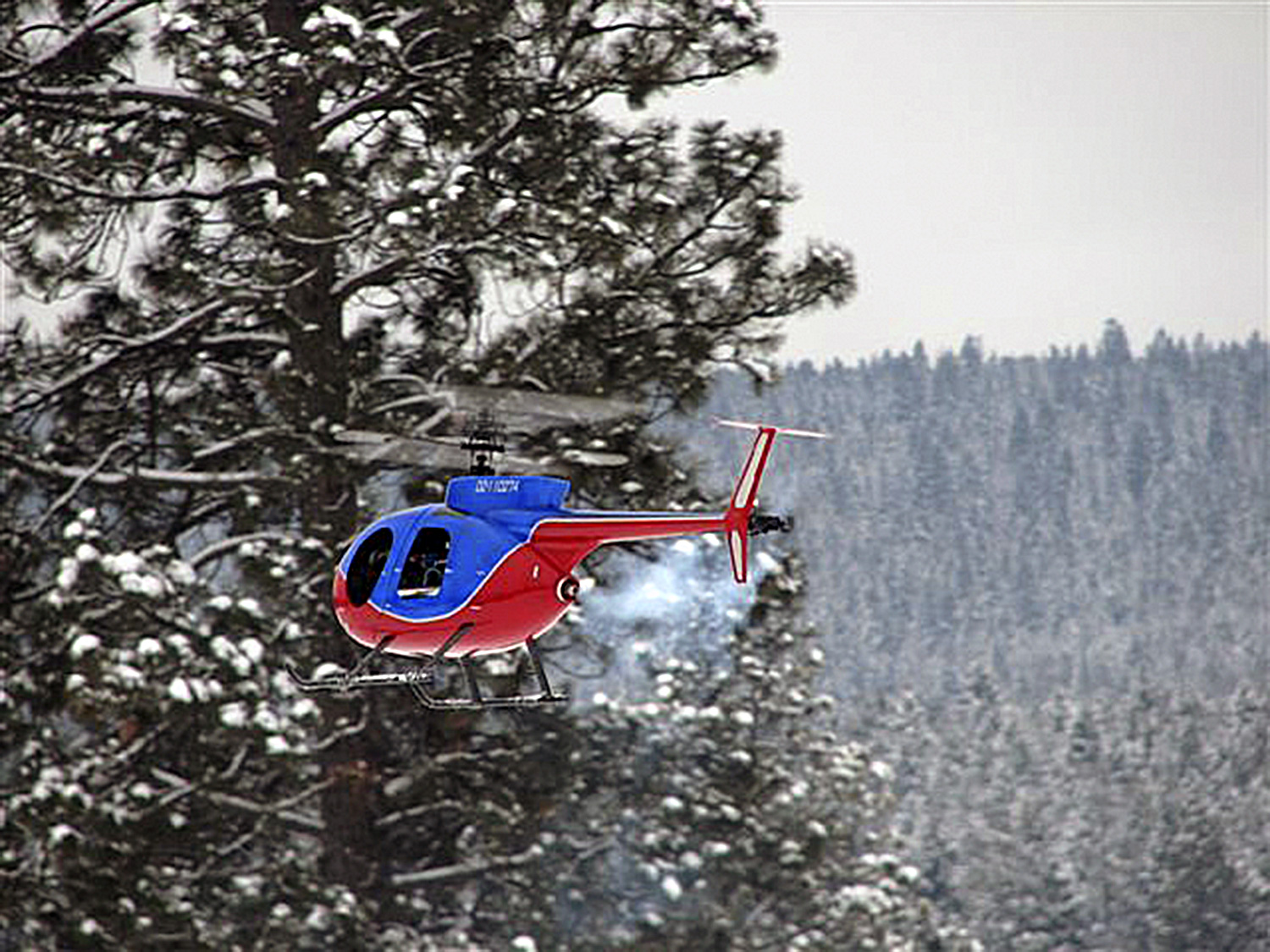
Basic Procedure
Installation is about the same-same whether it's a set of our mechanics, or another brand's because like dancing the Texas Two-step, everybody follows the same sequence. Gotchas and pitfalls we're going to discuss involve what to do when fitting your mechanics isn't a walk in the park.
Means we're going to touch on issues with shimming, or spacing the frames up off the deck (for tail drive alignment) and trimming (going lower than the existing deck). Trimming also comes into play whilst cutting back fiberglass around the tail case and swashplate, but like shimming, that's a very easy job.
Decking is trickier, but we'll show this also despite P6 mechnics being a simple bolt-in for the Funkey Hughes 500D just involving trimming fiberglass around the tailcase and swshplate. Nevertheless, we'll show how to solve installation problems you may encounter by showcasing other fuselage installations.
We're opening this can of worms because scale is the red headed stepchild of modeling (and helicopters even more so) and these tricks make it easier. We'll also show installations problems using a BK 117 (to illustrate decking), and two vertically challenged fuselages, a Bell 222 and Agusta A109 because when the mechanics themselves are too tall, the solution is to trim them, instead! We'll show you all of this.
Anyway, flying in a fuselage in America pretty much means even average pilots get a pause in the action because the models are somewhat unique stateside. Europe and Asia is the other way and over there, everybody flies models dressed in a fuselage because pod-and-boom is pretty much a flight training thing only.
So because stateside so few pull the trigger on a fuselage, you'll stand out from the pod-n-boom herd. Why? Dont really know, maybe it's like in high school, it's screwing up the nerve to ask a girl to dance.
Anyway, this scaleGUIDE is offered because we love models clothed in fuselages versus hopes of selling a single added P6 airframe.

Regarding the steps
The first step is aligning the tail drive with the boom to establish the basic height of the mechanics within the fuselage. The next step is sliding the mechanics fore/aft to align the main shaft position before marking, drilling, and bolting them in place. But step one usually involves some shimming and trimming, beforehand.
Since shimming and trimming can be tricky, to help with this, we're sharing photos and video of projects that aren't of this Hughes 500D (into which P6 mechanics 'do' drop right in) because there are broad similarities regarding how problems fitting helicopter mechanics get sorted. So to help, additional photos include Jet Ranger, BK 117, two different Agusta A109, plus an Ecuriel. Saying don't get flustered because we've switched fuselages on you!
Anyway, and as projects go, slipping a set of mechanics into a fuselage is actually the easy part, about 3 of 10. The real work involves details like the paint scheme, plus the small touches that bring the project to life. Talking about added details like a Spectrolab Nightsun searchlight, which can be bought or made by adapting a small flashlight then either fixed in place facing forward, or steered using a servo.
Other popular scale touches include navigation lights of which there are many vendors. But let me tell you, you can go absolutely crazy with details in helping complete the illusion of reality . . . and for some, these are actually a measure of how sick you are!

Note; the above photo is of my Blackhawk and small touches like rivets, wiper, step, and door hinges are the details where the rubber meets the road. But because these represent a significant time commitment, especially if this is your first go at a scale fuselage, then they're probably best off just adding a set of nav lights and leaving rivets for the future. That said, the best part of scale modeling is . . . you work to your standards, not ours.
So while it's my opinion a couple evenings laying out panel lines and rivets isn't really all that much work, even for a first scale model, you do you! That, and during a slow 10mph cruise-by, nobody is inside your head appreciating the aircraft like you, so whether you detailed it, or not, this model is about you instead of others!
Anyway, as you'll see, slipping mechanics into a fuselage is an easy project.

Components
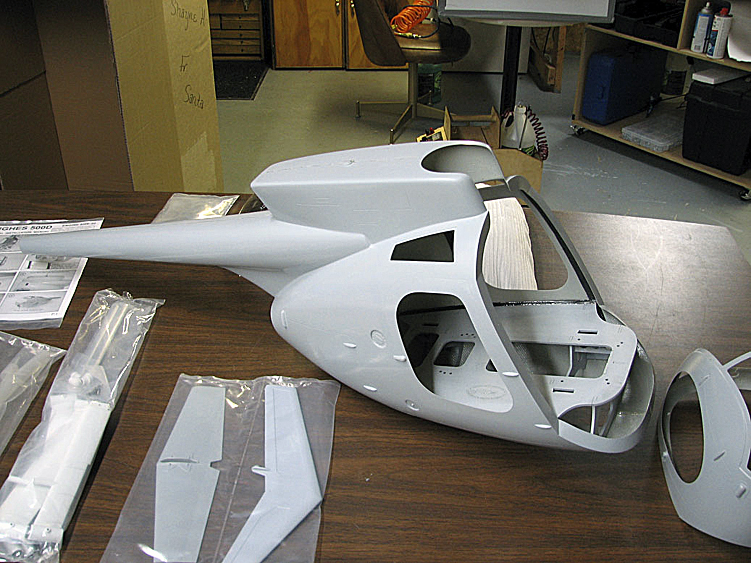
When you open the box and begin retrieving components you're presented with the main fuselage (actually, the aft portion with tail boom incorporated). Also, the forward fuselage section (where the glazing or windscreens are installed). There are also bags for fins, landing gear, plus some hardware used in the installation. But note; some models are so large the boom itself may be a separate component, I have a Bolkow BK-117 fuselage set up like this.
Anyway, this 500D sports one of my favorite features of Funkey brand FRP fuselages . . . the entire forward part comes off to create extremely easy access. Note; I don't have a dog in the hunt because we don't sell fuselages. I only mention this particular benefit as a builder's consideration.
To better appreciate the differences in access, eyeball this next photo of a lovely Graupner Agusta A109 fuselage. This fuselage offers more limited access to the mechanics because once you insert and bolt the mechanics down, from there on, working on this thing is limited to going in through the top and sides.
Of course, this isn't the end of the world, but I find working this to be a considerable pain in the hind end. So in comparison, and despite being workable (proof being the thousands of models flown this way), if I have a choice I prefer fuselages with better access.

Shimming
So I've mentioned shimming and trimming are the basics involved when fitting the mechanics. Shimming is an easy concept. Basically you add material as needed to raise a frame set into position for aligning the tail drive mechanism. Depending on the FRP fuselage and how they envisioned installation, some mechanics will need a little shimming, some may need a lot. Note; this Funkey Hughes 500D doesn't need any!
Goal is to raise the bottom of the frames above the (usually) preinstalled plywood formers within the fuselage. This, to get the tail drive gear aligned with the boom. However, some fuselages may require lowering, instead. This means trimming and we'll get to that in a bit.
Anyway, adapting mechanics to the fuselage is what involves your modeling skills. And this, after all, is where your inventive genius comes into play. For many, it's a great part of the fun!
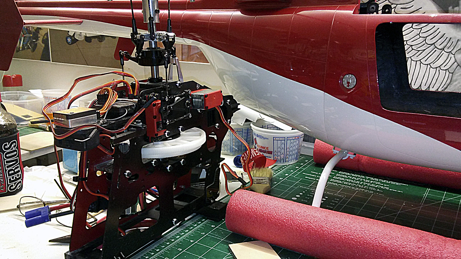
In this next photo, useful despite using another brand's mechanics, Larry Bailey shares how he used small blocks fitted beneath the frame's landing gear mounts to raise the tail drive into alignment. This made duck soup of fitting these particular mechanics into a Jet Ranger fuselage!
Trimming
While it's common as dirt during installation for mechanics to involve shimming to raise the tail drive into alignment with the tail boom, sometimes we have to do the opposite, lower the mechanics. There are two ways to accomplish this; either trimming the formers to lower the deck (decking), or trim the mechanics themselves. We'll show you both methods! Afterwards, you'll slide the whole thing fore and aft to center the main shaft.
Decking
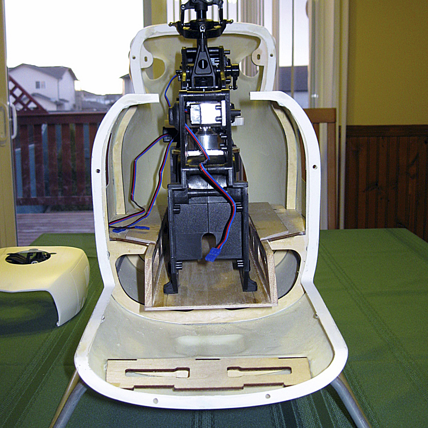
This next example shows how yet another of our customers, Svend Petersen, sectioned the plywood deck of his MBB117 fuselage (Messerschmitt-Bölkow-Blohm). I especially appreciate his showing the way because I have one just like it! Anyway, this fuselage needs trimming to allow the mechanics to go lower to achieve boom-alignment. Think this is too much work, trouble? For some? Maybe yes - but - it's actually quite an easy job.
Point being, sure Svend could have cut his loses and given up on the installation - but - he didn't. Instead, he forged ahead and cut out a piece of the plywood deck (the term is sectioning) and made it work. Anyway, P6 side frames are about 2-1/4" across the landing gear mounts, so he sectioned a piece of the 1/8" plywood deck about 3" wide. Next, he cut himself a substitute piece of deck material juuuust enough wider than what he cut out to account for the risers. And just eyeballing it; it looks to be about 3-1/2", or enough to account for a pair of 1/4' thick risers. Honestly? Easy job! Major point being, once epoxied back together, the mechanics fit perfectly and Bob's your uncle. From this point, the mechanics are now ready for fore/aft alignment of the main shaft.
Shimming summary
Once you get into fuselages, you're going to discover many models will require some shimming and trimming to make it work. Why? Simple, it's because sometimes fuselages are designed with one specific brand of mechanics in mind. So when the fuselage is subsequently purchased with an entirely different set of mechanics, a bit of modding will be involved. And quite honestly? For the fuselage to be taller or shorter than the mechanics for getting perfect boom-alignment is quite common so these tips will prove useful going forward.
Fortunately, trimming isnt the end of the world. And note; while in the above photo Svend used 3mm plywood for the deck, since 2mm carbon fiber sheet is readily available online, you have alternatives.
Before moving on, take another look at a small detail, a craftsman's touch. Svend lightened the risers by removing excess material. Probably used a Dremel with sanding drum for this. And if we're being honest, it's a trivial amount of weight, but he was working to his standards, not ours. Point being, when you're modding the fit of formers and braces, you get a lot of design freedom. And this is a huge part of the attraction for modelers who don't 'want' to fly the same thing as their buddy!
So next, let's consider what happens when there's nowhere to go . . . like what if you can't trim down anything within the fuselage because the mechanics themselves are too tall to begin with? Looks impossible, right? It aint!

Frames
But a trickier job is trimming side frames instead of the fuselage. Anyway, in a little bit, I'll share a brief how-to video about this sweet Agusta A109 fuselage I bought on the cheap (painted and everything) because the seller gave up once he discovered his mechanics wouldn't fit. And without disclosing who killed Cock Robin, all we did was cut down a set of Pantera side frames (using a Dremel jigsaw since they're plastic).

That, plus a couple short pieces of aluminum angle purchased from the hardware store resulted in a lovely installation. Honestly? It was also an easy job (especially as a set of plastic side frames makes it like new again if you change your mind, or subsequently want to repurpose the model back to trainer duty).
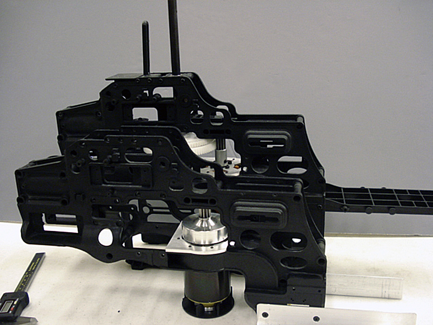
Trimming side frames
So the above photo shows the end results of trimming the sideframes instead of the decking of the fuselage. You can get away with this with many mechanics, not just ours, but it's especially easy job with a P6 because of our use of plastic instead of carbon fiber for the side frames.
Next, this brief video demonstrates the end results of this process. My pal Steve Poretz (who developed our 4-blade rotor head), worked with me on this project. Nothing hard about it, but it does involve a spot of lateral thinking as we set out to stuff a set of Pantera mechanics into the fuselage of a Hirobo-brand Agusta A109 fuselage I got a great deal on only to discover the mechanics were too tall and there was nothing to section. So when the fuselage is vertically challenged, trimming frames is an alternative approach.
Sounds scary, easy in practice. Anyway, this example which epitomizes . . . where there's a will, there's a way!
Recapping; lowering the deck of the Hirobo A109 fuselage wasn't an option. Instead of giving up, we whacked the side frames themselves. All told, the job took less than an hour. Major point being, endeavor to think around corners instead of boxing yourself into thinking you can't make something work.
Fore/aft alignment
Once the frames are fitted to give you the correct height, the next step is trivial in comparison. You're going to slide the frames fore aft to find the 'right' spot for the main shaft. Then make marks as needed, and if a bit of trimming is called for and break out your tools of choice, often the Dremel Rotary. And yes, here we have yet another easy job!

Clearancing around swashplate
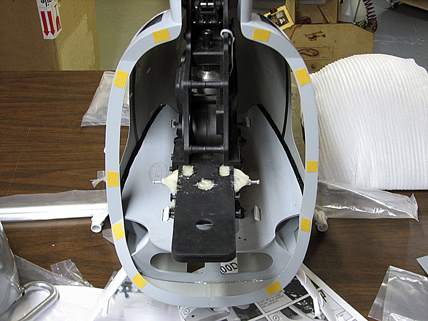
So for this particular installation, a spot of clearancing is called for around the main shaft to allow room for the swashplate and linkages. Svend marked this with a Sharpie and then made the cut. Easy peasy! Afterward, it's time to bolt the mechanics into place - yippee!
Note; ignore the white-ish epoxy/cotton reinforcing the forward canopy supports, this is a pro tip from our manual as preventative, or for repairing the battery tray following a crash that breaks them off to save a few bucks. And as for the yellow rectangles? Double stick tape as an aid whilst fitting things!
Painting
So in this next photo, three weeks have gone and we see a painted model. But that's not the full story because Svend actually painted the fuselage, twice. You see, after deciding on a paint scheme, and after filling pin holes, sanding, and the usual prep and after laying on the color and clear coats . . . he changed his mind!
Yup, saying he began with a color scheme and once he was done, he subsequently stripped the fuselage and started over - sigh. Happens when what's in your mind's eye and reality clash. Fortunately, not the end of the world but a bit of a messy job.

Anyway, for this scheme, the painting system per Sven was Klass Kote, a 2-part epoxy system with its own clear. He adds, Very easy to use and holds up well to nitro. Me? I've used Klass Kote and it handles just about exactly the same as the old school Petit Hobbypoxy (out of business) and K&B Superpoxy paints (also out of business).
These days, however, I mostly use 2-pack automotive paints (DuPont is basically my goto these days). However, I have also used an acrylic latex water based system, also . . . yes, house paint! Advantage is the paint is cheap and cleans up with water. Google is your friend as many articles exist for shooting latex house paint on scale model airplanes. And of course, paint and fiberglass don't know if it's a fuselage for an airplane of a helicopter!
Note; I do, however, shoot a coat of clear Klass Kote over latex paint jobs if I'm using regular model airplane/helicopter type fuel when I'm done because raw nitro in the fuel (if you spill it on the fuselage) will damage it if it's not wiped up immediately. And for gasoline fuel and electric powered models? Don't bother!
Note; all these paints work fine for a fiberglass fuselage and hold up to the knocks of life - but - this is an area where I'm going to suggest using whatever you're familiar with.

Lighting
So circling back to before installing the mechanics for the last time, because as regards . . . what's next? Sven installed a set of navigation and position lights from an outfit called MaxxLights. He also installed anti-collision, landing, and search lights!
Me? I like going to Dave's RC Electronics for lighting. Again, no dog in the hunt because we don't sell this stuff. I just like using Dave's because he's a very nice guy, knowledgeable, and offers the good stuff - recommended. So in this next photo we see the rotating beacon (red per regulations).

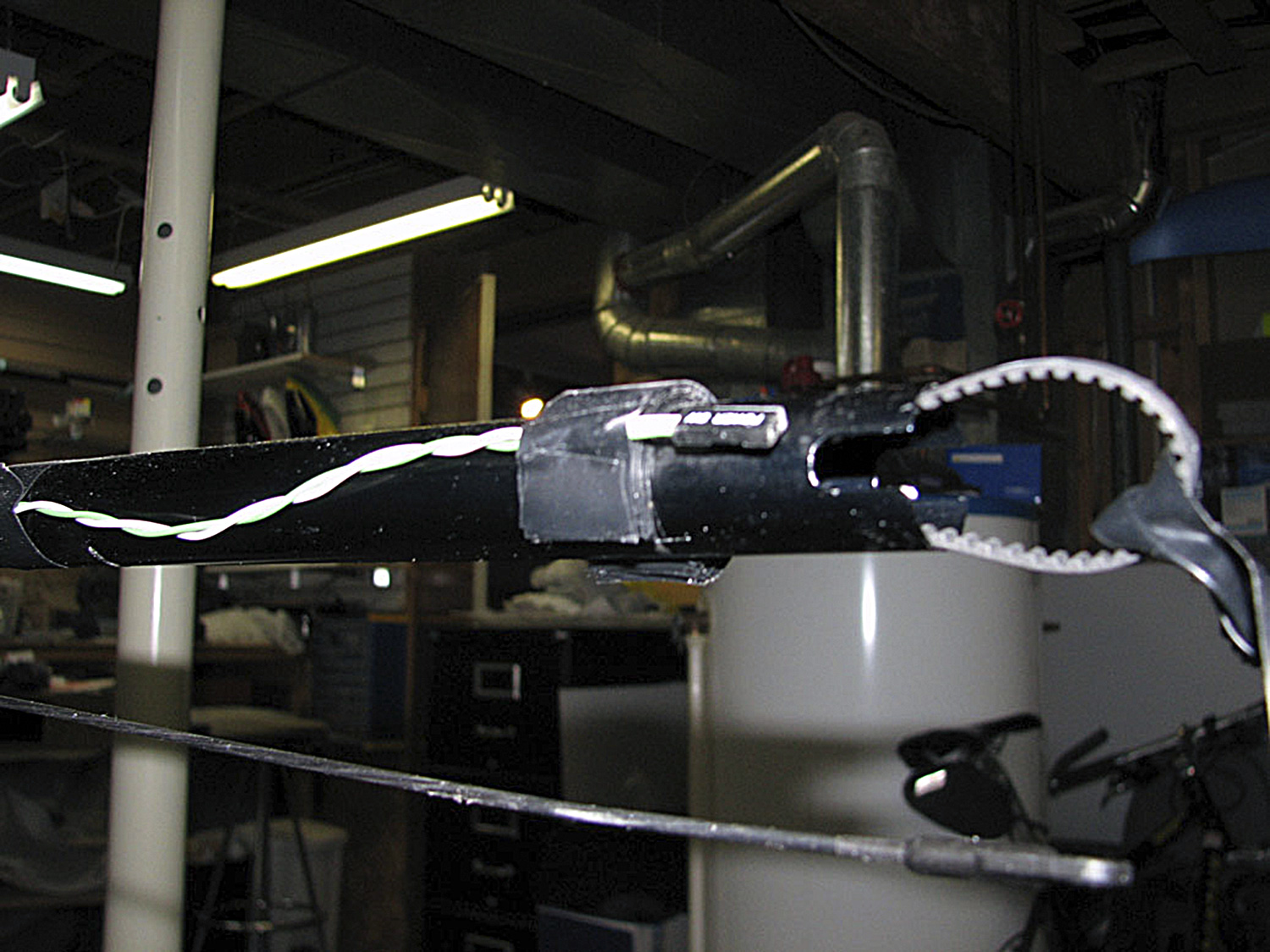
By the way, the tail strobe is an important lighting component present in full scale aircraft, both fixed and rotary wing. For your installation, you can do what he did (me as well) and simply use a wrap of electrical tape on the boom to hold the wires in place. And while some guys like to use Zip ties, I don't - preferring instead - the electrical tape because I've experience vibration chafing the insulation on a set of lighting leads, once, but macht nichts!
Note; since the foam insert supplied with the kit for supporting the model's tail boom within the fuselage's fiberglass tail boom was not a great fit, Svend resorted to a few extra wraps of electrical tape to shim the gap. Says it turned out perfect. Also, what you see on the end of these wires is actually the connector, not the LED itself, which is similarly tiny.
Test fitting
Anyway, from here, the last step is test fit and assembly. Here's where you finally test the lights to ensure they're doing what you expect of them.
Finally, best advice as regards lighting is this; place the nav lights, landing, and search lights on independent switches for best scale effect. After all, landing lights are only used whilst in the hover and during the actual landing, and not whilst flying around where they would look positively stupid!

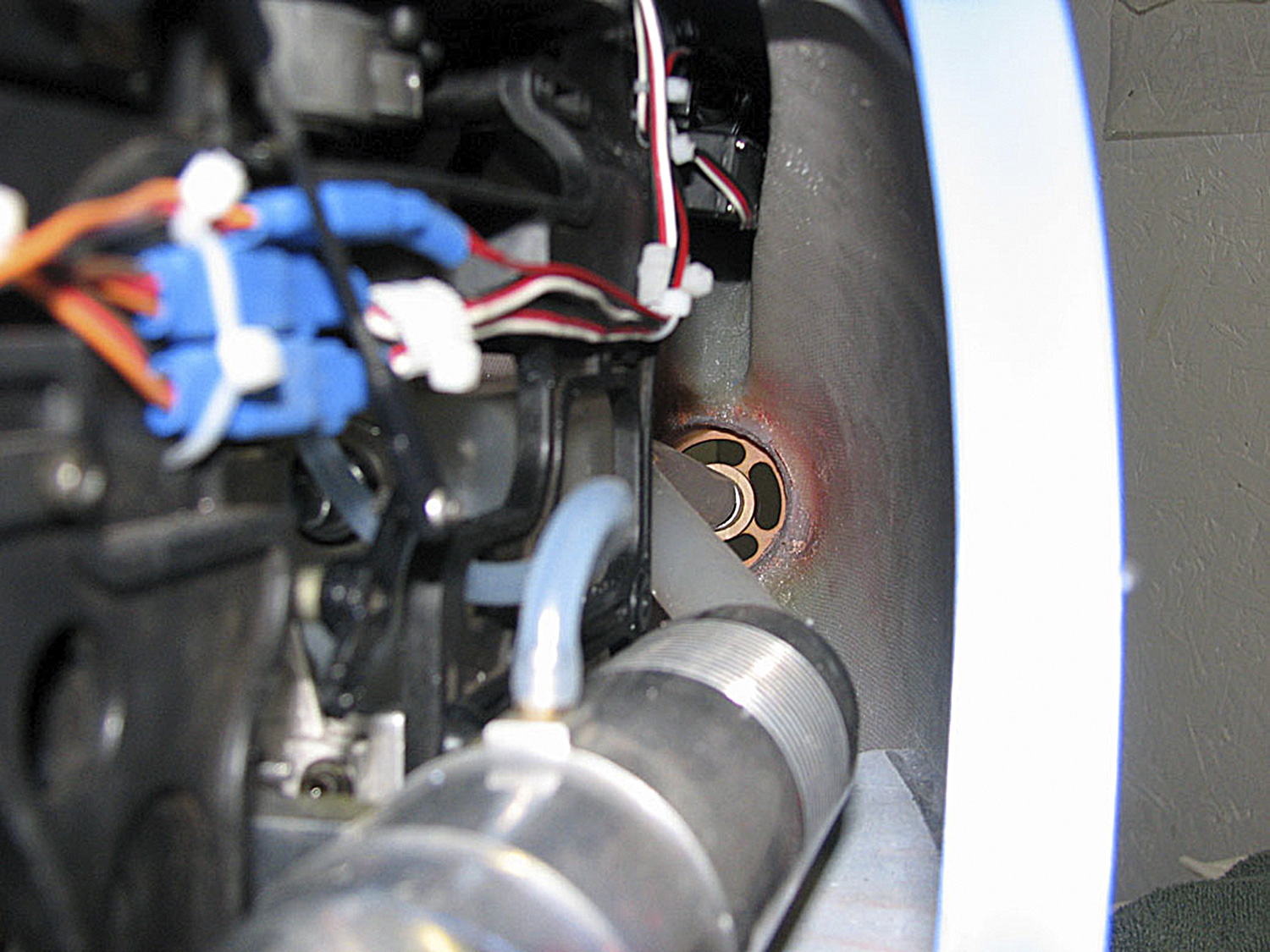
In this next photo we get a better look at the fit around the swashplate, which in the P6 moves up and down so it needs a few millimeters of clearance for the linkages/pushrods.

Final details
A few more things and we'll wrap this up. It’s critical to ensure the tail pushrod operates freely and doesn't hang up where it exits the fuselage. This is important to gyro function.
Note; Sven is using the heavy duty tail case option which has a more pointed look. Personal choice.
He's also using a set of 95mm carbon fiber tail rotor blades, which he trimmed down to 90mm. Again, personal choice.
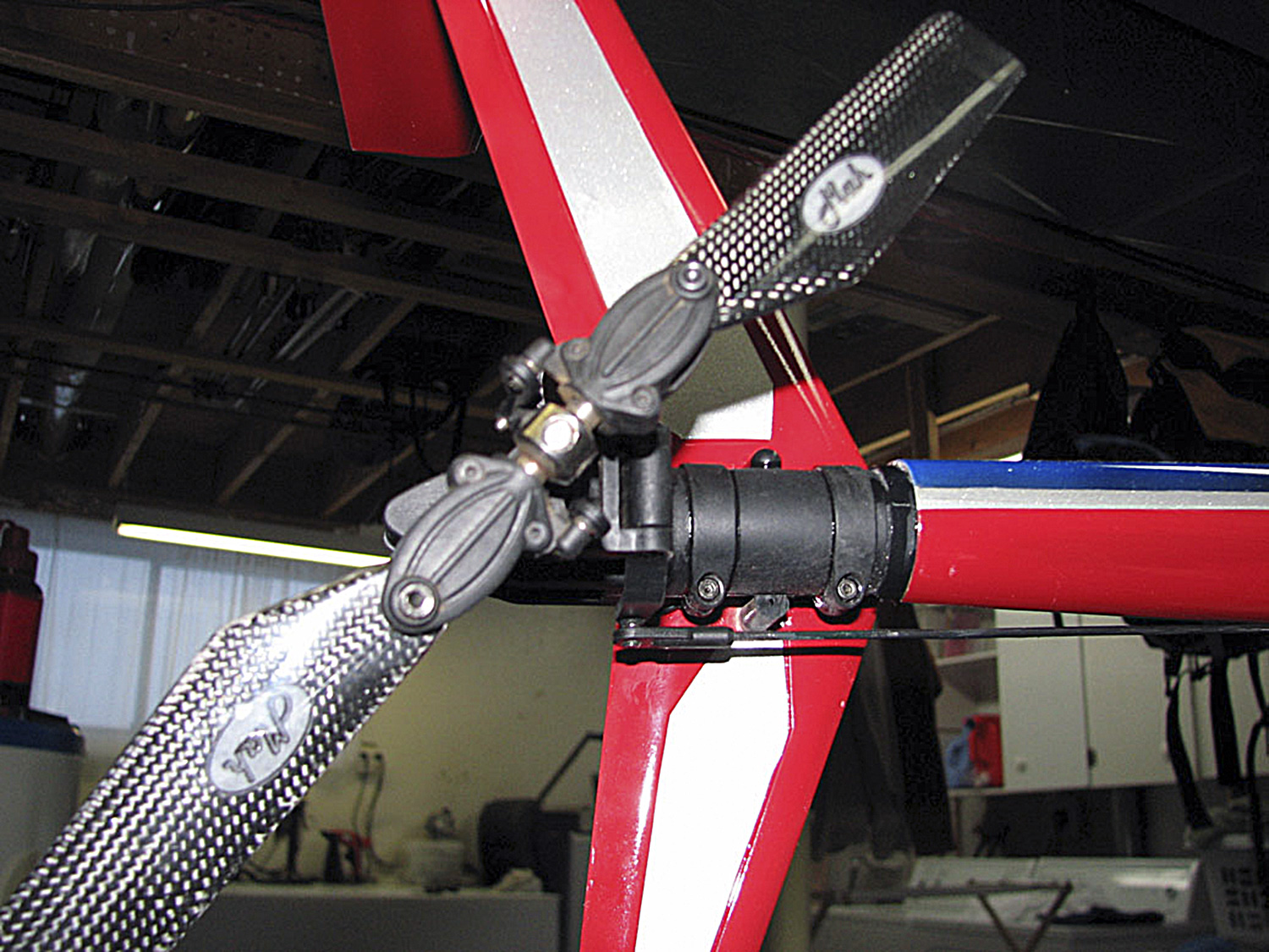
He did quite a neat job of it.
And this is about it, time to put the model away in preparation for the first clothed flights. And this brings up an important point. The first flights aren't with a brand new model. Instead, you should have flown in in the pod-and-boom configuration to give it a good shake down, e.g. trimmed, engine running good, etc.

Heads up on fitting in
Note; if you relish being made welcome at a fixed-wing field, the secret is fitting in with the normal air operations.
By this, we mean maneuvering exactly like 1:1 helicopters whilst at airports across the country. Fundamentally, this means flying the model as if it were full scale. This is because owning a scale model does not just mean looking the part, but flying the part, also because all aviators follow the same rules.
What this means in practice is departing from the runway instead of from the pit area like a hooligan. It also means flying the established patterns and circuits used by fixed wing pilots. And this isn't exactly easy because, for example, a properly executed hover taxi (straight down the centerline, with no variance in altitude) isn't exactly a walk in the park. If you're an experienced 3D pilot, you should try this particular maneuever to gain an appreciation of how hard flying scale-like can be. This, because it's a significantly trickier gig to pull off than piroflips, which I've personally witnessed a motivated 3D pilot master with a little help from a simulator in just one afternoon!
Anyway, and if you'll allow me a small plug, part of the reason a Pantera excels at scale flight is because it's so steady. Basically, you'll quickly get comfortable farting around down low, which by the way, is simply great fun! There's even a term for it, nap of the Earth.
Bottom line? Working to fit in means both you and your model will be welcome at model flying fields across the country. Choosing not to by hogging the runway with endless hovering and performing stupid pilot tricks (defined as ones, which impedes the pleasure of others by occupying the center of the field for prolonged period), means you'll not only get an earful (thus, explaining why at some flying fields, helicopters aren't welcome). So please don't be part of the problem!


